 The
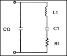
quartz crystal may be represented by the L,C,R circuit (Right).
 An oscillator is an amplifier with a feedback loop from output to input. Barkhausen criteria states that for oscillation to occur the product of the gains around a loop must be equal to or greater than unity and that the sum of the phase shifts around the loop must be a multiple of 360°.
Before beginning a design or purchase of an oscillator there are system parameters, which the oscillator will need to conform to. Below are questions which need to be determined by your system. These parameters will determine the type of oscillator you will require (TCXO, TCVCXO, VCXO, Clock, Ovenized).
 The
quartz crystal may be represented by the L,C,R circuit (Right).
C0 is the capacitance formed by the crystal electrodes plus any holder capacitance. The L1, C1, R1 branch is called the "motional arm". The motional capacitance, C1, controls the "pullability" of the crystal. The shift of a crystal can be calculated by the following formula:
![]()
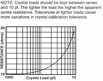
Knowing two different loads on the crystal, we can look at the differences between each shift from series to calculate the total trim range. C1 and R1 can be specified on any crystal. Typical values of R1 are 10 to 25 ohms on the fundamental mode and higher on overtones. Typical motional capacitance values are between 0.018 pf and 0.024 pf for a fundamental crystal. Motional capacitance is divided by the overtone squared. Static capacitance (C0) is about 213 times C1 on the fundamental mode.
L1 can be calculated knowing the series frequency of the crystal.
Example: given a 0.020 pf C1 and a C0 of 4.26pf the shift from series of a 20pf load is 412.2 ppm and the shift of a 27 pf load is 319.9ppm. This gives us a tune range of 92.3ppm between 20 pf and 27 pf loads.
 |
 |
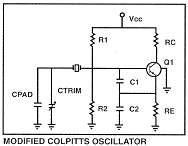
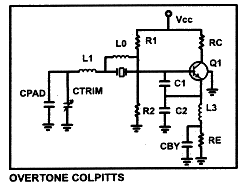
The oscillating loop C1, C2 in parallel with RE, Ctrim in parallel with Cpad and the crystal can be isolated from load effects in the colpitts oscillator by keeping RC«RE. The output waveform at the collector is highly distorted due to the self-limiting of the oscillator drawing pulses of collector current. The trimmer in this design has only a second order effect on loop gain. The loop gain in this circuit is controlled by the gain of the transistor and the reactance and ratio of C1 and C2. To begin with the reactance of C2 should be -j75 ohms and the reactance of C1 should be slightly larger.
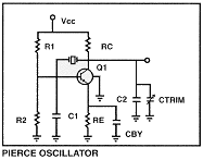
PIERCE OSCILLATOR
 |
 |
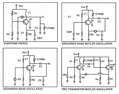
The oscillating loop C1 in parallel with R2, Ctrim in parallel with C2 & Rc and the crystal is directly tied to the load causing poor load stability. The trimmer is across one of the feedback capacitors and directly effects loop gain. The output waveform at the collector is relatively sinusoidal.
The design considerations are the same as the modified colpitts oscillator. Tune C2 and L3 to the frequency directly between the desired overtone and the overtone just below. Choose values of C2 and L3 such that Xc2 in parallel with XL3=-j75 ohms. The static capacitance of the crystal can be canceled by placing an inductor across the crystal, from the crystal to ground or from the crystal to the emitter of the transistor. This will increase the drive on the crystal. Cby is used to increase the Q of the trap.

L1//C2 form a trap in the same manner as C2//L3 in the colpitts oscillator. Choose L1 and C2 in the manner outlined in the "Overtone Colpitts" design. As in the colpitts design, an inductor can be added to tone out the effect of the crystal's static capacitance (CO).

These oscillators may be tuned initially by placing an AC short across the crystal and tuning Ctrim. These are basically amplifiers with a tapped capacitor resonant circuit in the collector. The tapped capacitor should match the impedances of the input and output. In the "Grounded Base Butler" Oscillator the loop gain may be increased by shunting Re.
Crystal Load Capacity = Series
TWO TRANSISTOR BUTLER
The butler oscillator has the ability of high frequency good load stability and output amplitude gain. This circuit is commonly used in wide pull VCXOs and TCVCXOs.
Crystal Load Capacity = Series
